- If you need clarification, ask it in the comment box above.
- Better answers use proper spelling and grammar.
- Provide details, support with references or personal experience.
Tell us some more! Your answer needs to include more details to help people.You can't post answers that contain an email address.Please enter a valid email address.The email address entered is already associated to an account.Login to postPlease use English characters only.
Tip: The max point reward for answering a question is 15.
Forgive me, not advertising for these guys, http://www.laptopkeyboard.com/Guides.php/Samsung/Q%20Series/Q430/KBSG5 (They say, "A picture is worth a thousand words") As new as the Samsung Q430 series of Notebook PC's is, there should be only two different types of ZIF connectors on the motherboard, used for the Keyboard Cable. But may be three; A ZIF connector is a Zero Insertion Force connector. The motherboard connector on a laptop, that the Keyboard Cable goes into, is a style of ZIF connector. Usually composed of two parts; The bottom part is larger in size, and is Stationary to the motherboard. It is called the BODY. The upper part is smaller in size, and is Movable. It is the Locking Bar. Uses the wedge principle when in the closed/locked position, to wedge the Keyboard Cable into the Body. 1) The newest style has no Locking Bar to release. The Keyboard Cable is gently, yet firmly, pulled on; and removed from the motherboard connector. To reinstall just line it up as it was originally, then push in. 2) I refer to this as the Flip-Up style; Closed/Locked, http://www.irisvista.com/tech/laptops/Toshiba-Satellite-L645D-L640D/big/laptop-disassembly-13.jpg Open/Unlocked, http://www.irisvista.com/tech/laptops/Toshiba-Satellite-L645D-L640D/big/laptop-disassembly-14.jpg 3) And an older style. I refer to this style as the Slide style; Closed/Locked; http://www.irisvista.com/tech/laptops/Toshiba-Satellite-L675D-L670D/big-body/dismantle-laptop-10.jpg Open/Unlocked; http://www.irisvista.com/tech/laptops/Toshiba-Satellite-L675D-L670D/big-body/dismantle-laptop-11.jpg All you can see are two 'Tab's of the Locking Bar, on each side of the Keyboard Cable. These Tabs are EASED up with your thumbnails. Ease up on one side a little, then the other side; then both sides. Moves approximately 2mm. That is a little more than 1/16th of an Inch, or about the width of this capital letter -> O <- IF,....the Locking Bar is broken, or IF,...the Body is broken; you are looking at MOTHERBOARD REPLACEMENT, and why I am being so detailed. Note that other motherboard connectors, may use a ZIF connector of one of the types stated above, also. Touchpad Cable, etc. When replacing a Keyboard, line the flat bar terminals strips on the Keyboard Cable, back up to the contact pins in the motherboard connector. The Keyboard Cable MUST go back in the same position, as it was originally. Therefore look at the old Keyboard, and it's cable; to orient the new Keyboard Cable correctly. For additional questions please post in a Comment. Regards, joecoolvette
NOTE that there is no connector attached to the cable. Just exposed flat contact pins. These contact pins MUST line back up, as when the cable was originally installed.
For this reason I suggest making a mark (Sharpee?), on one side of the cable, and a matching mark on the same side of the motherboard connector; BEFORE removing the Keyboard Cable from the motherboard connector.
Gives you a reference as to which way the new Keyboard Cable goes, when installing the new Keyboard. Twisted, flipped over,....going to Florida for vacation; the new Keyboard Cable MUST go back same position, as the old Keyboard Cable.
What he is depressing are 3 spring Detent's above the Keyboard. Approximate locations; A) Above the F2 and F3 keys B) Above the F7 and F8 keys C) Above the Prt Scr and Pause/Break keys.
Small rounded tabs. Along the lines of this Asus K53u laptop example,
Look at Step 6 and Step 7 photos. I use a flat tip Jewelers screwdriver. Be gentle so you do not scratch the plastic. Start on the Right side, gently depress the Detent, and at the same time use a fingernail to gently lift up on the upper right side of the Keyboard, a little.
Now go to the middle Detent, and finally the Detent on the Left. Lift the Keyboard on the LCD screen side up, JUST A LITTLE. Then slide up towards the LCD screen, Just a Little.
There are plastic tabs formed out of the Keyboard on the side facing you. If you bring the Keyboard straight up, you chance breaking those tabs off. Tabs cleared, roll the top of the Keyboard, (LCD screen side), towards you. Be gentle as the Keyboard Cable is STILL attached; you can only go so far.
The motherboard connector is a type of ZIF connector. Zero Insertion Force. It is composed of two pieces, but does NOT come completely apart.
Three styles are used, two currently to my knowledge. Yours is the Flip Up type.
The bottom part is rectangular in shape, and is the larger piece. It is stationary to the motherboard, and is called the BODY.
The top part is also rectangular in shape, and is the smaller of the two parts. It is movable, and is called the Locking Bar.
IF, the Locking Bar comes off of the Body, it is broken; or the hinge pins in the Body the Locking Tab hinges on; are broken.
This = MOTHERBOARD REPLACEMENT, and why I am being so detailed. Be G-E-N-T-L-E with this connector.
1) Remove ALL power. Remove the AC adapter, (Charger), and Battery.
2) Click on the Blue - Dell Vostro 3500 Service Manual (8530KB)
[This is a PDF file. The computer you are using now has Adobe Reader on it, which uses PDF files. After you click on the file name it may take up to 30 seconds, before the first page comes up ]
In the Service Manual click on the blue - Removing and Replacing Parts
Click on Keyboard in the right list.
NOTE* The Keyboard Cable STAYS attached to the Keyboard. It removes from the motherboard connector. There is NO plug connector on the motherboard side, of the Keyboard Cable.
The Keyboard Cable is a FFC. Flat Flex Cable. This is a general example of a FFC,
Note the flat metal strips. These are Contact Strips. They mate up to Contact Pins, in the motherboard connector. The Keyboard Cable MUST be reinstalled, as it was in the original position.
For this reason you may wish to make a mark, (Sharpee?), on one side of the Keyboard Cable; and a matching mark on the same side of the Keyboard Cable motherboard connector.
The motherboard connector is a type of ZIF connector. Zero Insertion Force. It is rectangular shaped, and composed of two parts, BUT does NOT come completely apart.
The bottom piece is the larger of the two. It is stationary, and mounted to the motherboard. It is the Body.
The top piece is also rectangular in shape, smaller in size, and is movable. It is the Locking Bar. The Locking Bar is designed to wedge the Keyboard Cable; in the Body, when in the Locked position. (Closed)
IF, the Locking Bar is removed from the Body, it is Broken. IF, the Locking Bar is broken, or the Body, you are looking at MOTHERBOARD REPLACEMENT, and why I am being so detailed.
Use your thumbnails, or fingernails, to EASE open the Locking Bar. (Unlocked) Metal tools have the tendency to slip, and break the motherboard connector.
There are Three types of Locking Bars used, to my knowledge. (Forgot about one in the past) The Slide type, and the Flip Up type.
I can't make out in the Service Manual what style is used. I think it is the Flip Up type. However;
The Brown tabs pointed out by the Yellow arrows, are the sides of the Locking Bar. These are what is eased forward by the thumbnails. The distance is 2mm. That is a little more than 1/16th of an Inch, or about the width of this capital letter -> O
A) Remove ALL power. Remove the AC adapter (Charger), and Battery.
B) In the Irisvista link above, click on the photo shown in Step 6. Look at the Battery Compartment area at the top. Note the two rubber 'feet' on each side.
The 3 screws that are circled in Red, and are to the inside of the rubber feet, should be removed. I think they hold the Keyboard Securing Strip on.
C) Follow Steps 8 through 12 on the Irisvista link above. (You are on Page 1. Page 1:: Page 2:: Page 3:: Find another model, is on the top of the page, and bottom of the page in White.
A note on the Keyboard Cable;
The Keyboard cable STAYS attached to the Keyboard. It removes from the motherboard's connector.
The Keyboard cable is a FFC. Flat Flex Cable. This is one general example of a Flat Flex Cable,
The thin metal strips on the end of the cable, (Will be motherboard connector side), are contact pins. This end of the cable slides into the motherboard connector. It is on the opposite side of the Keyboard.
Before removing the Keyboard Cable from the motherboard connector, you may wish to make a mark on one side of the cable; and a matching mark on the Same side of the motherboard connector. (Sharpee?)
Even if the cable was twisted from the factory, it MUST go back the same direction it was removed.
The motherboard connector is a type of ZIF connector. Zero Insertion Force. It is rectangular in shape, and is composed of two parts. HOWEVER, it does NOT come completely apart.
The bottom piece is the larger of the two parts. It is the BODY. The upper smaller rectangular piece is the Locking Bar.
The Locking Bar moves. The Body is stationary, and mounted to the motherboard. The Locking Bar works on a wedge type of principle, and when it is in the locked position, it wedges the Keyboard Cable in the Body.
There are two types of Locking bar used at present, to my knowledge. I cannot discern in the Irisvista photos, as to which type is used.
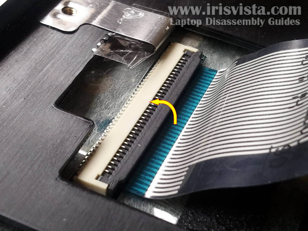
Here you can see the Body is White in color, and the Locking Bar is Brown. You can also see that there are essentially two 'tabs', of the Locking bar showing; on either side of the Keyboard Cable.
One uses their thumbnails to Gently ease the Locking Bar forward; and towards the LCD screen.
The Locking Bar ONLY moves about 2mm. That is a little more than 1/16th of an Inch, or about the width of this capital O.
IF, the Locking Bar is broken; and/or the hinge pins for the Locking Bar on the Body, are broken; you are looking at - MOTHERBOARD REPLACEMENT, and why I am being so detailed.
I do not have access to my Toshiba laptop Service Manuals, anymore. According to the Irisvista link there are NO screws, that come up from the bottom of the laptop; and screw into the bottom of the Keyboard.
However I wish you to look FIRST, before trying to remove the Keyboard. If present these screw/s will be in an area under the laptop, that corresponds with the area of the Keyboard.
Generally are in the Battery Compartment, and can be seen when the Battery is removed. May also be situated as stated, in the area of the Keyboard. Usually they/it will have a K next to them/it, or Keyboard, or a Keyboard symbol.
For additional questions please post in a Comment. Regards, joecoolvette
The flat metal terminal bars MUST be aligned back in the SAME position, as they were originally. For this reason you may wish to take a Sharpee marker, and make a mark on one side of the cable. Then make a matching mark on the same side of the motherboard connector, BEFORE you remove the cable.
The motherboard connector is a type of ZIF connector. Zero Insertion Force. It is composed of two pieces, but does NOT come completely apart!
The bottom part is larger, rectangular shaped, and is stationary to the motherboard. It is the BODY.
The upper part is smaller, rectangular shaped, and is movable. It is the Locking Bar.
ACCORDING to the video the Locking Bar is the Slide/Wedge type.
DO NOT use a metal tool as shown. One slip, and you can damage the motherboard! Geez!
Use your Fingernails, or Thumbnails.
The Locking Bar slides up. Up towards the LCD screen, or away from the Body. It ONLY moves about 2mm. That is a little larger than 1/16th of an Inch.
IF, the Locking Bar is broken, or the Body, you are looking at -> MOTHERBOARD REPLACEMENT!!
Hence why I am being so detailed.
More detail on unlocking this type of motherboard ZIF connector,
It has NO connector on the end. The connector is on the motherboard. The Keyboard cable STAYS with the Keyboard. It disconnects from the motherboard.
The connector on the motherboard is a type of ZIF connector. Zero Insertion Force. It is composed of two pieces, but DOES NOT come completely apart.
It is rectangular in shape. There is a larger rectangular part for the bottom. This is the BODY. There is a smaller rectangular part on top. This is the Locking Bar.
When the flat cable is inserted into the motherboard connector, closing the Locking Bar wedges the cable into the Body. Locks the cable in place.
(BEFORE removing the Keyboard Cable from the motherboard connector, suggest you make a mark on one side of the cable, and a corresponding mark on the same side of the motherboard connector. The cable MUST go back into the motherboard connector, the same way it came out. The flat contact strips of the cable, have to line back up with the contact pins in the motherboard's connector )
FROM WHAT I SEE in the Service Manual, the Locking Bar appears to be the type that flips up. The side nearest the cable is the side that comes up.
USE CARE. IF, the Body is broken, or the Locking Bar, you are looking at -> motherboard replacement. Hence why I am being so detailed.
The Wireless Antenna cable (1) comes apart. Use care, and pull the connector apart. The Video Cable (2) unplugs from the motherboard. (Display Cable = Video Cable)
For additional questions please post in a Comment.
1) Always remove ALL power remove the AC adapter (Charger), and Battery. 2) Use a multi-compartment container for the various screws you will remove. Label each compartment for the area the screw/s come out of. SOME screws look VERY similar to other screws. Advise DO NOT mix them up.
As you can see viewing down the various photos in the pictorial guide, the Top Cover, along with the Display Assembly, is removed. Has to be removed in order to access the Power Button Board.
In order to remove the Top Cover, the Keyboard is one of the items to remove first. Look at Step 4.
The Keyboard Cable STAYS with the Keyboard. It removes from the motherboard connector. Again,....Removes FROM the motherboard connector.
The Keyboard Cable is a FFC. Flat Flex Cable. It has NO connector on the cable. The connector is on the motherboard, and stays on the motherboard.
The connector on the motherboard is made of two pieces. It DOES NOT come completely apart!
If it is in two pieces it is broken, and you are looking at motherboard replacement. Hence why I am being so detailed. Do not break it!
The motherboard connector has a larger bottom rectangular piece, which is the BODY. It has a slimmer rectangular top piece, which is the Locking Bar.
The Locking Bar is wedge shaped. When locked into position in the Body, the wedge shape wedges the Flat Flex Cable, and locks it in.
The Locking Bar is Brown. All you will actually see are two tabs of it. One tab on one side, and one tab on the other side. Use your finger/thumbnails, and ease the tabs towards the cable itself. (Away from the Body of the motherboard connector)
If you look close at Steps 4 and 5, you can see the brown tabs of the Locking Bar have been moved forward, and away from the Body. The Locking Bar ONLY MOVES about 1 to 2 Millimeter's.
[2mm is a little larger than 1/16th of an Inch. 1mm is a little larger than 1/32nd of an Inch. Use a tape measure to compare, or another measuring device ]
I just searched to find a replacement Power Button Board. No luck on this end, hope you have better.
Most laptop keyboard are secured by screws on the bottom of the laptop. The screws that fix the keyboard may have a tiny heyboard symbol against the screw. When you remove the keyboard screws you can then lift the keyboard off the laptop. The keyboard is connected to the motherboard via a flat ribbon cable, it may have a connector on the cable or a locking clip on the motherboard. Release this ribbom cable from the motherboard, don't pull on this cable or you may damage the ribbon cable.


×