At Fixya.com, our trusted experts are meticulously vetted and possess extensive experience in their respective fields. Backed by a community of knowledgeable professionals, our platform ensures that the solutions provided are thoroughly researched and validated.
I just need a fuse box diagram for a 1995 Pontiac grand prix SE. i know where the fuse box is located but my car didnt come with a cover and i just realized my tail lights are out so i need to find out which fuse is which so i can fix it
Ignition Switch
GM Century/Lumina/Grand Prix/Intrigue 1997-2000
The vehicles covered by this guide use one of two types of ignition switches:
A mechanical key and lock cylinder built into the steering column, that works a pull rod to actuate the separate electrical portion of the ignition switch mounted further down the steering column. For more information and replacement procedures on this type of switch, please see .
An instrument panel-mounted ignition switch is also used on some W-Body vehicles. To service this switch, the radio, heater & A/C control panel and the instrument cluster must be removed. All of these procedures are found elsewhere in this section.
REMOVAL & INSTALLATION Instrument Panel-Mounted Ignition Switch
WARNING
You must perform the Body Control Module (BCM) theft deterrent relearn procedure after replacement of the ignition lock cylinder. Failure to perform this relearn procedure means the BCM will not function properly. This means the vehicle will not be theft protected by the Passlock system and the engine may not crank or start. GM recommends that this procedure be performed with their Tech 2® or equivalent scan tool. An alternate relearn procedure is given at the end of this procedure.
Disconnect the negative battery cable.
Remove the radio assembly following the procedures found in this section.
Remove the heater & A/C control head assembly following the procedures found in this section.
Remove the instrument cluster assembly following the procedures found in this section.
Detach the electrical connectors from the ignition switch.
Insert the key and turn the ignition switch lock cylinder to the ACC position.
Depress the transaxle park/lock cable retainer to release, then pull to remove the cable from the ignition switch.
NOTE
You must perform the Body Control Module theft deterrent relearn procedure after replacement of the ignition lock cylinder.
If it is necessary to remove the ignition lock cylinder from the ignition switch (theft damage, etc.), use the following procedure:
Insert the key and turn the ignition switch lock cylinder to the ON position.
Using a small flat-bladed tool, depress and hold the lock cylinder retaining tab.
Using the key as an aid, pull to remove the ignition switch lock cylinder from the switch.
Remove the key from the lock cylinder.
Carefully pull to release the ignition switch bezel from the ignition switch lock cylinder.
Remove the ignition switch bracket bolts and remove the ignition switch through the instrument panel cluster opening.
Remove the bolts retaining the ignition switch to the bracket and remove the bracket.
Install the ignition switch to its bracket and install the bolts. Install the ignition switch into position through the instrument panel cluster opening and install the bracket retaining bolts.
If removed, install the ignition switch lock cylinder to the ignition switch using the following procedure:
Recode the lock cylinder, if necessary.
Align the ignition switch bezel to the tabs on the ignition switch lock cylinder and carefully press to secure in place.
Insert the key and turn the ignition switch lock cylinder to the ON position.
Align the ignition switch lock cylinder to the ignition switch, then press into place.
Turn the key to the ACC position. Align and press into place the transaxle park/lock cable to the ignition switch. Remove the key from the switch.
Attach the electrical connectors to the ignition switch.
Install the instrument cluster using the procedures found in this section.
Install the heater & A/C control panel using the procedures found in this section.
Install the radio assembly using the procedures found in this section.
Connect the negative battery cable.
If the lock cylinder was removed, perform the BCM Programming/RPO Configuration procedure.
yes it will fix your cigarette lighter. open the door on the drivers side and crawl in there and look up to your left it should be right there use a flash light .. good-luck ray
If you are looking for a wiring diagram for the fuse box then there are a couple of sources. Pickup a hayes or chilton repair manual from a local parts store or go online to ALLDATA. com. You will have to pay for the info online, but you can print it off. You can search for the wiring info online for free but I have had little success that way. If you are looking for fuse locations within the fuse box then try the owners manual in the glove box or buy a manual.
- If you need clarification, ask it in the comment box above.
- Better answers use proper spelling and grammar.
- Provide details, support with references or personal experience.
Tell us some more! Your answer needs to include more details to help people.You can't post answers that contain an email address.Please enter a valid email address.The email address entered is already associated to an account.Login to postPlease use English characters only.
Tip: The max point reward for answering a question is 15.
Question edited for clarity.
Questions moved to a better category.
If all of those are blown, you are in for a whole lot of heartache! Cigarette lighter overloaded, easy fix. Blower motor, probably the resistor, fairly easy fix if you can get to it. Windows, relays, or if only on drivers side, broken wires where door meets frame.
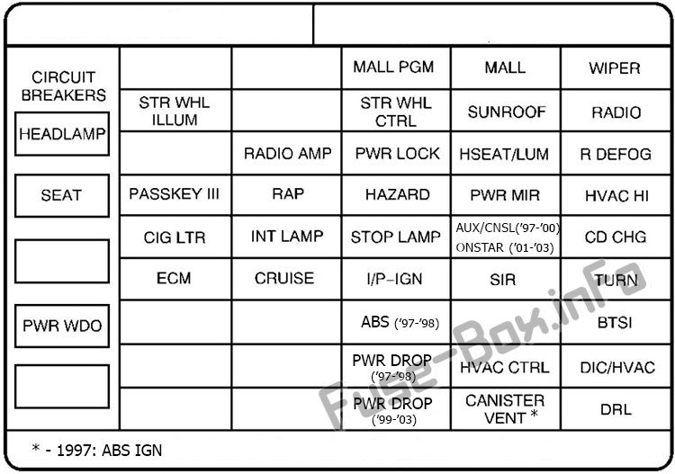
https://fuse-box.info > Home > Pontiac
Fuse box diagrams (location and assignment of the electrical fuses and relays) ... fuses and relays) for Pontiac Grand Prix (1997, 1998, 1999, 2000, 2001, ...
 Removing an instrument panel-mounted ignition switch assembly—1998 Oldsmobile Intrigue shown, others similar
To install:
Removing an instrument panel-mounted ignition switch assembly—1998 Oldsmobile Intrigue shown, others similar
To install:


×