I believe that this is what you are looking for.....
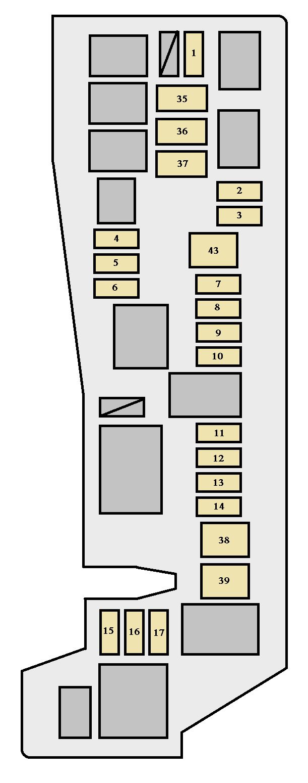
Fuse and relay locations--2nd generation power distribution box Layout-
I think this is a good sticky candidate--

Fuses are listed here
* = maxi fuse
1*=50A I/P fuse panel
2*=40A blower motor relay3*= 50A 4 wheel ABS module
4*=20a Main light switch-Instrument cluster
5*=50A Ignition switch, starter relay
6*=20A Transfer case relay
7*= NOT USED
8*=20A Auto Ride Control Switch/on off switch
9*=40A Auto Ride Control relay
10*=30A PCM power relay
mini fuses
1=10A A/C relay
2=20A Aux power point
3= not used
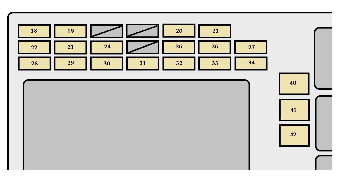
4=15A Fog lamps-Daytime lamps
5=10A Air Bag diagnostic monitor
6=10A Powertrain Control Module (PCM)7=30A 4WABS module
8=30A PCM relay
9=20A Fuel Pump relay and RAP module
10= 15A Horn relay
11=15A Park Lamp relay-Main Light Switch
12=30A Main light switch--Multi Function switch
13=15A Heated O2 sensors, EGR Vacuum Regulator, EVR solenoid,Camshaft position (CMP) Sensor,
Cannister Vent Solenoid, A4LD Auto Transmission14=30A Generator-Voltage regulator
Interior fuse panel (mini fuses)
1=7.5A Power mirror switch
2=7.5A Blower motor relay,PAD module,Air Bag diagnostic monitor3=7.5A Trailer tow connector
4=10A Left headlamp
5=10A Data link connector (DLC)
6=7.5A Air bag diagnostic monitor, Blower motor relay, Passive deactivation Module (PAD)7=7.5A Trailer Tow connector
8=10A Right headlamp, Daytime running lamps (DRL) module, Foglight relay
9=7.5A Stop Lamp switch
10= 7.5A Speed control-amplifier assembly,Brake pressure switch, Generic electronoc Module (GEM)
Shift lock actuator, Blend door actuator, Main light switch, RABS resistor, A/C heater assembly
Flasher
11= 7.5A Instrument cluster, Main light switch, RABS resistor12= 10A Power window relay, Washer pump relay13= 20A Stop lamp switch, Brake pressure switch
14= 20A Rear Anti Lock Brake system (RABS) module**10A 4WABS module**
15=7.5A Instrument cluster16= 30A Windshield wiper Motor, Wiper Hi-lo relay, wiper run/park relay
17=7.5A Cig lighter
18=15A Drivers unlock relay-All unlock relay
19=25A PCM power diode
20=7.5A RAP module GEM module, Radio
21=15A Flasher (hazard)
22=20A Aux power socket
23=15A Turn signals
24===not used
25= 7.5A GEM module, Instrument cluster26= 10A Battery saver relay, Electronic Shift relay, Interior lamp relay
Power window relay,Electronic shift control module, transmission control27=15A Switch,DRL, Backup lamp switch, DTR sensor,Instrument illumination dimming control module
Dome/map lamp, GEM,electronic shift,Interior lights,Glove box lamp and switch
28=7.5A GEM module-Radio
29= 15A Radio
30=15A Park lamps, trailer Tow relay
31===not used
32=10A rear blower
33=15A Headlamps, DRL module, Instrument cluster34=7.5A Rear integrated control panel, CD
35=10A RABS test connector
36=7.5A CD, rear integrated control panel, memory seat, Message center
Attached images

__________________


×