Front I/O - Computer cases also come with various LEDs (lights showing hard-drive activity, for example) along with reset and power buttons. These also need to be connected to the motherboard, hence these cable slots.

Hello? Tap, tap on the monitor. What are you reading from?
http://www.ebay.com/itm/Acer-MB-NB107-001-DA061-078L-Motherboard-eMachines-08120-2-780G-AM2-Desktop-/280919767281?pt=Motherboards&hash=item41681f78f1
The front of your computer is the Front Panel.
The area of contact pins on the motherboard, that the main wires go to from the Front panel, is the Front panel header.
Motherboard installed in computer, the Front panel header is at the Bottom/Right.
Two rows of 7 pins in a small black rectangular plastic block.
http://www.ebay.com/itm/Acer-DA061-078L-Motherboard-eMachines-EL1200-X1200-AMD-780G-Socket-AM2-DDR2-/140825131784?pt=Motherboards&hash=item20c9d4fb08
TOP row of pins is numbered EVEN.
BOTTOM row of pins is numbered ODD.
Starting on the LEFT side going towards the Right, TOP row:
Pins 2, 4, 6, 8, (NO 10), 12, and 14. Again, there is NO Pin 10.
Starting on the LEFT side going towards the Right, BOTTOM row;
Pins 1, 3, 5, 7, 9, 11, and 13.
A) Pins 1 and 3 are for the HarDDrive activity LED. (Light)
Pin 1 is for the Positive ( + ) wire.
If the HDD LED is dim when the harddrive is active, switch the wires around.
2) Pins 5 and 7 are for a Reset switch, IF a Reset switch is used.
3) Pins 2 and 4 are for the Power On LED (Light)
Pin 2 is for the Positive ( + ) wire.
If the PWR LED is dim when the computer is on, switch the wires around.
4) Pins 6 and 8 are for the Power On switch.
5) The rest of the pins are N/C. Not Connected.
Don't forget to plug the 4-pin ATX +12 Volt power cable in,
(Top left corner),
http://www.playtool.com/pages/psuconnectors/connectors.html#atx12v4
For additional questions please post in a Comment.
Regards,
joecoolvette
And how is it with the front audio and mic? what pins to use?
how is it with the front audio and mic connectors? where to put them?
First of all, thank you to whoever rated this solution! Second, @Karl; Don't know. Bit I bet after you, and I get together; I will. Even looking at this large photo of the mobo,http://www.codemicro.com/store/product/M... (Click on the photo. Takes a second, or two); I couldn't make out what is silkscreened on the motherboard, next to these headers. (All the headers to the left of the Front Panel header) From what I can see there looks to be two headers for USB. Each one will support two USB ports. I do see a header in the middle, (Black; 3-pin), that looks to be the Clear CMOS jumper header. What does it state in white silkscreen, under those headers Karl? Also, here is a regular USB pinout for a desktop motherboard,http://attachments.techguy.org/attachmen... ,and here is a standard USB pinout, (Male and Female plug/connector),http://pinouts.ru/Slots/USB_pinout.shtml Just remember which end you are following, and follow the wires.
This is a picture from my computer, th mb is not exatly tha same as on the other picture. The name om my MB is da061/078L-AM3. It says under the pins (upside down) AUDIOF1, and the other pins SPDIF

Hey Joecoolvette! You are a legend! Thank you
×
SOURCE: configuring motherboard powerswitch leds reset
u will find front pannel connection pins on mother board. its in 2 lines. in onle row there is one pin slot idle. next to that vacant pin slot u insert reset sw, next to it insert hdd led, behind hdd led insert power led, next to power led (behind reset sw) insert power sw. thats it done
SOURCE: need to re-attach power button cable, hard drive
The manual for your computer is available from emachines, p.168 shows the info you need (replacing the front I/O panel)
http://downloads.emachines.com/userguides/8511279_eM_NG3_chassis_HW_ref_en.pdf
The good news is that you can't harm the computer by connecting the wires wrong and the bad news is they just won't work the way they are supposed too if not connected properly. The LED's must have the correct polarity to work.
In general, if you look real close (as in magnifying glass and flash light) you will see the ID for each set of pins is printed on the motherboard (pwr,rst,HDD,pwr sw,speaker) Just match what it says on the motherboard to what it says on the wires. Don't worry if you get the polarity wrong. If a light doesn't work just swap the two wires. The colored wires should be positve (+), though. The reset (rst) and power switch (pwr sw) wires don't require polarity.
These instructions are for most computers in general, YMMV.
Testimonial: "Thanks, have a good one!"
SOURCE: connector diagram to acer ms 6772 motherboard needed
most motherboards have labels wherein you should connect the power button. facing the motherboard, try looking for it on the lower right.
SOURCE: Need wiring diagram for eMachine 20030812 motherboard!!!
You should be able to see the words/letters that go with the jumpers on the motherboard itself. look around the jumper settings area for power, pwr etc. and match them up with your jumpers which should have what the go to on them.
SOURCE: need front panel connection diagram power switch lrf connectipns on 9 pin connector on motherboard
Hi u can easily solve this problem.
open your computer cover and and see the motherboard front panel connectors. a use of screw driver touch any two front panel connectors if any led or switch working this condition you can note this and connect successfully. one by one touch all penal connections and u will be solve ur problem thanks mukesh kumar
[email protected]
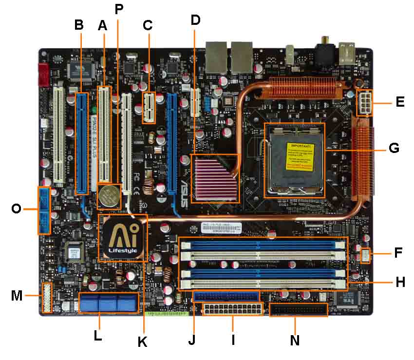 Once you know what you are looking at, you can recognize the components on any motherboard layout. A computer motherboard diagram is very useful for when you need to replace motherboard, do motherboard upgrades, troubleshoot motherboard, or build your own computer.
23,823 views
Usually answered in minutes!


×